

OSI Model Visualization: Understanding the Seven Layers
Introduction
The OSI (Open Systems Interconnection) model is a conceptual framework used to understand and standardize the functions of a telecommunication or computing system. Developed by the International Organization for Standardization (ISO) in 1984, it divides network communication into seven distinct layers, each with specific responsibilities.
Understanding the OSI model is fundamental for network engineers, system administrators, and anyone working with network technologies. This guide will provide a comprehensive overview of each layer, their functions, protocols, and how data flows through the model.
The Seven Layers of the OSI Model
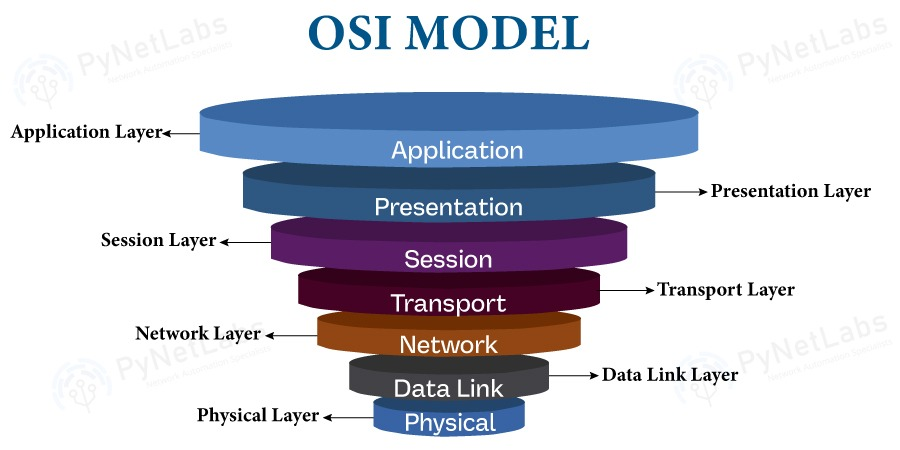
The OSI model is often visualized as a stack, with Layer 7 (Application) at the top and Layer 1 (Physical) at the bottom. Data flows down through the layers when being sent and up through the layers when being received.
Layer 7: Application Layer
Purpose: Provides network services directly to user applications.
Functions:
- User interface for network services
- Network access for applications
- Error recovery and data integrity
- Identification of communication partners
Protocols and Examples:
- HTTP/HTTPS: Web browsing
- FTP: File transfer
- SMTP: Email sending
- DNS: Domain name resolution
- SSH: Secure shell access
- Telnet: Remote terminal access
Data Unit: Data/Message
Key Points:
- This is the layer users interact with directly
- Applications like web browsers, email clients operate here
- Does not include the application itself, but the protocols it uses
Example: When you type https://example.com in a browser, the Application layer uses HTTP/HTTPS protocol to request the webpage.
Layer 6: Presentation Layer
Purpose: Translates, encrypts, and compresses data for the Application layer.
Functions:
- Data translation (encoding/decoding)
- Data encryption/decryption
- Data compression
- Character code translation (ASCII, EBCDIC, Unicode)
Protocols and Examples:
- SSL/TLS: Encryption (though often implemented at Layer 5 or 7)
- JPEG, GIF, PNG: Image encoding
- MPEG, AVI: Video encoding
- ASCII, Unicode: Character encoding
Data Unit: Data/Message
Key Points:
- Ensures data is in a format the receiving application can understand
- Handles encryption and compression
- Sometimes combined with Application layer in TCP/IP model
Example: Converting a text file from ASCII to Unicode, or encrypting data before transmission.
Layer 5: Session Layer
Purpose: Establishes, manages, and terminates connections between applications.
Functions:
- Session establishment, maintenance, and termination
- Dialog control (half-duplex, full-duplex)
- Synchronization (checkpoints in data stream)
- Session recovery
Protocols and Examples:
- NetBIOS: Network Basic Input/Output System
- RPC: Remote Procedure Call
- PPTP: Point-to-Point Tunneling Protocol
- SAP: Session Announcement Protocol
Data Unit: Data/Message
Key Points:
- Manages the "conversation" between two applications
- Can set up checkpoints for data recovery
- Often minimal in modern implementations
Example: When you log into a remote server, the Session layer establishes and maintains that session until you log out.
Layer 4: Transport Layer
Purpose: Provides reliable data transfer between end systems.
Functions:
- End-to-end error recovery
- Flow control
- Segmentation and reassembly
- Connection-oriented and connectionless communication
Protocols and Examples:
- TCP: Transmission Control Protocol (reliable, connection-oriented)
- UDP: User Datagram Protocol (unreliable, connectionless)
- SCTP: Stream Control Transmission Protocol
Data Unit: Segment (TCP) or Datagram (UDP)
Key Points:
- Ensures data arrives completely and in order (TCP)
- Provides port numbers to identify applications
- Handles retransmission of lost packets
- Critical for reliable communication
TCP Characteristics:
- Connection-oriented (three-way handshake)
- Reliable (acknowledgments, retransmission)
- Flow control (sliding window)
- Congestion control
UDP Characteristics:
- Connectionless
- Fast but unreliable
- No flow control
- Used for real-time applications (video, gaming)
Example: When downloading a file, TCP ensures all packets arrive and are reassembled in the correct order.
Layer 3: Network Layer
Purpose: Provides logical addressing and routing of packets across networks.
Functions:
- Logical addressing (IP addresses)
- Routing (determining best path)
- Path determination
- Packet forwarding
Protocols and Examples:
- IP: Internet Protocol (IPv4, IPv6)
- ICMP: Internet Control Message Protocol
- ARP: Address Resolution Protocol
- OSPF: Open Shortest Path First (routing protocol)
- BGP: Border Gateway Protocol (routing protocol)
Data Unit: Packet
Key Points:
- Uses IP addresses for logical addressing
- Routers operate at this layer
- Handles routing between different networks
- Does not guarantee delivery (that's Transport layer's job)
IPv4 vs IPv6:
- IPv4: 32-bit addresses (4.3 billion addresses)
- IPv6: 128-bit addresses (340 undecillion addresses)
Example: When you send data to a server on a different network, the Network layer determines the best route through routers to reach the destination.
Layer 2: Data Link Layer
Purpose: Provides error-free transfer of data frames between two nodes on the same network segment.
Functions:
- Physical addressing (MAC addresses)
- Error detection and correction
- Frame synchronization
- Media access control (MAC sublayer)
- Logical Link Control (LLC sublayer)
Protocols and Examples:
- Ethernet: Most common LAN technology
- Wi-Fi (802.11): Wireless networking
- PPP: Point-to-Point Protocol
- Frame Relay: WAN protocol
- ATM: Asynchronous Transfer Mode
Data Unit: Frame
Sublayers:
- LLC (Logical Link Control): Error control and flow control
- MAC (Media Access Control): Physical addressing and media access
Key Points:
- Uses MAC addresses (hardware addresses)
- Switches operate at this layer
- Handles errors within a single network segment
- Controls access to physical media
Example: When your computer sends data to another device on the same network, the Data Link layer uses MAC addresses to deliver the frame to the correct device.
Layer 1: Physical Layer
Purpose: Transmits raw bit stream over physical medium.
Functions:
- Physical connection between devices
- Bit transmission
- Signal encoding
- Physical topology
- Transmission mode (simplex, half-duplex, full-duplex)
Components:
- Cables (copper, fiber optic)
- Network interface cards (NICs)
- Hubs and repeaters
- Connectors (RJ-45, fiber connectors)
- Physical transmission media
Data Unit: Bit
Key Points:
- Deals with actual physical hardware
- Transmits bits (0s and 1s) as electrical, optical, or radio signals
- No logical addressing or routing
- Hubs and repeaters operate here
Transmission Media:
- Copper: Twisted pair (Cat5e, Cat6), coaxial cable
- Fiber Optic: Single-mode, multi-mode
- Wireless: Radio waves, microwaves
Example: When data is sent over an Ethernet cable, the Physical layer converts the digital bits into electrical signals that travel through the cable.
Data Flow Through the OSI Model
Encapsulation (Sending Data)
When data is sent, it flows down through the layers, with each layer adding its own header (and sometimes trailer):
- Application Layer: User data (e.g., HTTP request)
- Presentation Layer: Adds encoding/encryption
- Session Layer: Adds session information
- Transport Layer: Adds TCP/UDP header (port numbers, sequence numbers)
- Network Layer: Adds IP header (source/destination IP addresses)
- Data Link Layer: Adds frame header (source/destination MAC addresses) and trailer (FCS)
- Physical Layer: Converts to bits and transmits over medium
Decapsulation (Receiving Data)
When data is received, it flows up through the layers, with each layer removing its header:
- Physical Layer: Receives bits, converts to frames
- Data Link Layer: Checks MAC address, removes frame header
- Network Layer: Checks IP address, removes IP header
- Transport Layer: Reassembles segments, removes TCP/UDP header
- Session Layer: Manages session, removes session header
- Presentation Layer: Decrypts/decompresses, removes presentation header
- Application Layer: Delivers data to application
OSI Model vs TCP/IP Model
While the OSI model has 7 layers, the TCP/IP model (used on the Internet) has 4 layers:
| OSI Model | TCP/IP Model | Protocols |
|---|---|---|
| Application | Application | HTTP, FTP, SMTP |
| Presentation | Application | SSL/TLS, JPEG |
| Session | Application | NetBIOS, RPC |
| Transport | Transport | TCP, UDP |
| Network | Internet | IP, ICMP, ARP |
| Data Link | Network Access | Ethernet, Wi-Fi |
| Physical | Network Access | Cables, NICs |
Practical Examples
Example 1: Web Browsing
- Application: Browser sends HTTP request
- Presentation: Data formatted as HTTP
- Session: Session established with web server
- Transport: TCP ensures reliable delivery
- Network: IP routes packet to destination
- Data Link: Ethernet frame with MAC addresses
- Physical: Electrical signals over cable
Example 2: Email Sending
- Application: Email client uses SMTP
- Presentation: Email formatted and possibly encrypted
- Session: SMTP session established
- Transport: TCP ensures email arrives
- Network: IP routes to mail server
- Data Link: Ethernet frame
- Physical: Transmission over network
Example 3: File Transfer (FTP)
- Application: FTP client initiates transfer
- Presentation: File encoding handled
- Session: FTP session maintained
- Transport: TCP for reliable file transfer
- Network: IP routing
- Data Link: Frame delivery
- Physical: Bit transmission
Troubleshooting Using the OSI Model
The OSI model is excellent for troubleshooting network issues:
- Layer 7 Issues: Application not working, wrong protocol
- Layer 6 Issues: Encoding problems, encryption failures
- Layer 5 Issues: Session timeouts, connection drops
- Layer 4 Issues: Port blocked, connection refused
- Layer 3 Issues: Routing problems, wrong IP address
- Layer 2 Issues: MAC address conflicts, switch problems
- Layer 1 Issues: Cable unplugged, NIC failure, signal problems
Common Protocols by Layer
Application Layer (7)
- HTTP, HTTPS, FTP, SMTP, POP3, IMAP, DNS, DHCP, SNMP, Telnet, SSH
Presentation Layer (6)
- SSL, TLS, JPEG, GIF, PNG, MPEG, ASCII, Unicode
Session Layer (5)
- NetBIOS, RPC, PPTP, SAP
Transport Layer (4)
- TCP, UDP, SCTP
Network Layer (3)
- IP (IPv4, IPv6), ICMP, ARP, OSPF, BGP, EIGRP
Data Link Layer (2)
- Ethernet, Wi-Fi (802.11), PPP, Frame Relay, ATM, VLAN
Physical Layer (1)
- Physical cables, connectors, hubs, repeaters
Benefits of Understanding the OSI Model
- Troubleshooting: Systematic approach to network problems
- Communication: Common language for network professionals
- Design: Better network architecture decisions
- Learning: Foundation for understanding network technologies
- Certification: Essential for networking certifications (CCNA, Network+, etc.)
Conclusion
The OSI model provides a structured way to understand network communication. While modern networks primarily use the TCP/IP model, the OSI model remains valuable for:
- Learning networking concepts
- Troubleshooting network issues
- Understanding how different protocols interact
- Designing network architectures
- Professional certifications
Remember that in practice, some layers (especially Presentation and Session) are often combined or minimal, but understanding all seven layers gives you a complete picture of network communication.
Additional Resources
- ISO/IEC 7498-1:1994 - Official OSI model standard
- Network+ Certification materials
- CCNA study guides
- Wireshark documentation (for packet analysis)
Mastering the OSI model is a fundamental step in becoming a network professional. Practice identifying which layer different protocols and devices operate at, and you'll have a solid foundation for advanced networking concepts.